Please not that these features where implemented in the early stage, prior to logging the progress.
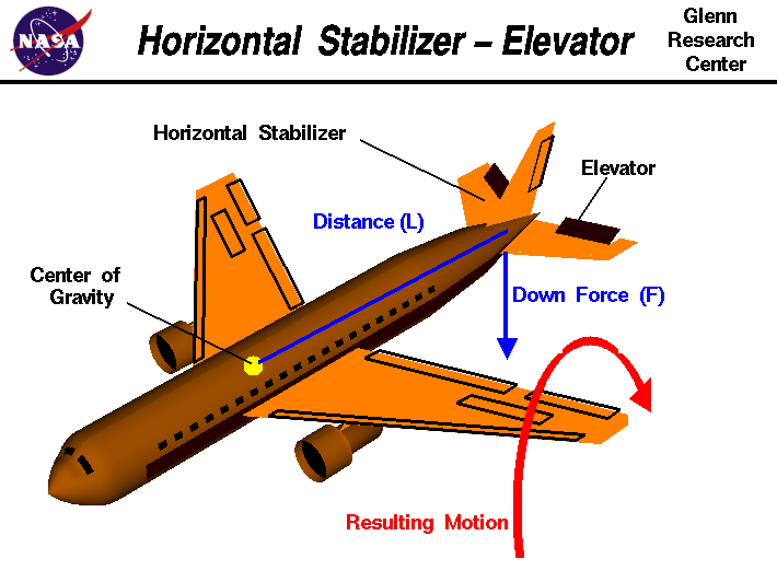
In Modeling part 2, equations of motions are added to the aircraft model. In the current state, the aircraft is modelled as A giant (and heavy) symmetrical flying wing. The B2-Spirit is designed in A similar way and it is aerodynamically unstable, constant relying on adjustments from flight control computers. Most aircraft need an extra mechanism for longitudinal stability. Adding A horizontal stabilizer/tail is a conventional way to add longitudinal stability and control.
Longitudinal stability
The stability of some system refers to the tendency to return to the original state after being disturbed by some external input, much like shooting a marble. In longitudinal flight, the disturbance is a pitch up or pitch down input. Static stability refers to the immediate response of the aircraft, i.e, you bump your hand against the stick, stick goes down, what is the response very shortly afterwards. Dynamic stability considers the motion over a longer period of time.
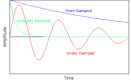
For a statically stable aircraft, if it is dynamically unstable, then it will keep oscillating about the equilibrium state, but the amplitude increases over time and so it diverges to some extreme. If it is dynamically netural, then it will oscillate, but the amplitude remains the same and it will continue oscillating indefinitely. If it is dynamically stable, it will oscillate, but the amplitude decreases over time (dampening) and it will subside to the original state. The amount of damping varies with aircraft design and the aircraft may be underdamped, overdamped and even critically damped.
If the aircraft is currently launched horizontally forward at an altitude of 20.000ft, it first pitches down slightly, then tend to pitch up (negative angle of attack), countered by a pitch-down and so on until this oscillation dies out. the trajectory is parabolic while this is happening. It tends to restore to the original state, zero angle of attack, but the trajectory is still downward. There will never be any moment equilibrium in the current state. The model is in need of some mechanism that counters the torque exerted by the main wing to allow steady flight.
Horizontal stabilizer (HSTAB)
If the result from part 2 is A flying wing, then applying the exact same equations using smaller dimensions will lead to A smaller flying wing. With the exact same procedure, a HSTAB is added to the current model and its location is behind the CG.
Analysis
Reconsidering the moments involved after adding the HSTAB:
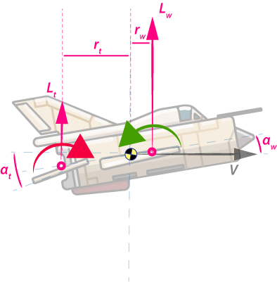
Note that the CG is centered this time. To simplify the illustration, drag forces are not included.
Notice that in this case the EOM are superpositioned:
\[\boldsymbol{ \tau_{total} = \tau_{w}+ \tau_{t} =r_w \sin{\alpha} D + r_w \cos{\alpha} L +r_t \sin{\alpha_t} D_t + r_t \cos{\alpha_t} L_t }\]where subscript \(w\) is the wing contribution and \(t\) is the tail/HSTAB contribution .
The extra term \(\boldsymbol{ \tau_t}\) allows control of pitching moment.From the diagram notice that, \(\boldsymbol{r}\), the arms determine the magnitude and sign of \(\boldsymbol{\tau_{total}}\) as do \(\boldsymbol{L_w}\) and \(\boldsymbol{L_t}\). \(\boldsymbol{r}\) is assumed fixed during flight (Assumption). The configuration of \(\boldsymbol{r}\) and the aerodynamics of the wing and tail will determine the stability of the aircraft.
Longitudinal Control
Control is added using flight control surfaces and in the longitudinal case this can be done using elevators, elevons, trim tabs, HSTAB trimming or using stabilators.
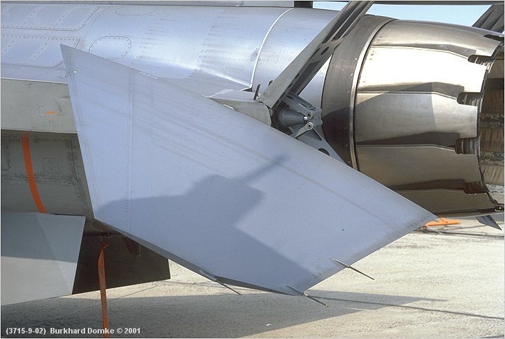
Stabilitor
The stabilator is a fully moving tail/HSTAB. Fighter aircraft mainly have stabilators. The simplest way out for now is to consider stabilators.
Analysis
Notice from the earlier diagram:
\[\boldsymbol{\alpha_t =\theta_t + \alpha_w}\]and recall from part 2:
\[\boldsymbol{ L_t = C_{L_t} \frac{1}{2} \rho v^2 S_t }\]To control the stabilator, \(\boldsymbol{\theta_t}\), the deflection angle (just like the pitch angle) must be controlled. If the stabilator can be controlled, \(\boldsymbol{ L_t}\) can be controlled so that the entire aircraft can be controlled by change in pitching moment.
Modeling
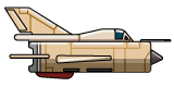
The stabilator of the MIG-21 is modeled and the airfoil is considered thin, symmetric. \(\boldsymbol{r_t}\) is fixed to some distance aft the CG, while \(\boldsymbol{r_w}\) is fixed to a small distance in front of the CG. The aircraft is configured to be aerodynamically stable. Control input is done via mouse input. The deflection angle of the stabilator is controlled directly via mouse input.
Result
It was a pretty tedious,maybe A bit aggrevating task to get the model to work . A big lesson learned is to keep track of sign conventions, because sign errors quickly accumulate and debugging will be like finding a needle in the haystack. The result is awesome:
TODO.
The stabilator is limited to 15 degree positive, 7 degree negative deflection:
 .
.
The aircraft is extremely sensitive to input, since there is nothing that limits deflection rate. As a result, the aircraft can be exposed to destructive G loads (>22g’s) at high speed. A pitch limiter needs to be implemented to safeguard the aircraft (who cares about the pilot right?).
Pitching moments, lift forces and arms are displayed during simulation. Dat.gui is used to inspect and change parameters during simulation.
What’s next
At this point, controlled flight is achieved.

Some possible improvements in flight control: trimming, damping, adding flaps, speedbrakes. The atmosphere is currently assumed to be a linear model, which is not true in reality. More about this in Modeling part 4: Modeling the atmosphere.